PRODUCT RECALL
H2S/H4S - Glow Plug Fault
Symptoms

- After normal start-up, the fan begins spinning.
- The diesel fuel pump activates, indicated by an audible ticking sound.
- The heating process does not initiate, and the unit only blows cold air.
- No white smoke is visible from the exhaust pipe.
- During the startup period, the total incoming power to the heating unit's power terminals is less than 50W when the glow plug should be active.
- The LCD controller displays Fault 10: Ignition Failure.
* All of the above criteria must be met to qualify for this recall.
OR
- The LCD controller displays Fault 90: Glow Pin Open Circuit.
Why Did HEATPORT Issue This Recall?
HEATPORT initiated this recall after identifying that a small number of heating units were assembled with a specific batch of glow plugs that could potentially fail prematurely. While these glow plugs passed initial quality checks and functioned correctly during testing, some units have exhibited the described symptoms after just a few days, weeks, or months of operation, resulting in potential ignition failures. Under normal conditions, these glow plugs are designed to last for years without failure, often throughout the entire lifetime of the product. To ensure the continued reliability of the product, HEATPORT has decided to proactively offer solutions to remaining customers. Even if you have not experienced the described fault, HEATPORT is offering a free replacement for any eligible heating unit as a precaution.
ELIGIBLE PRODUCTS:
Model: HEATPORT H2S / H4S
Date of manufacture: Early/Mid 2024
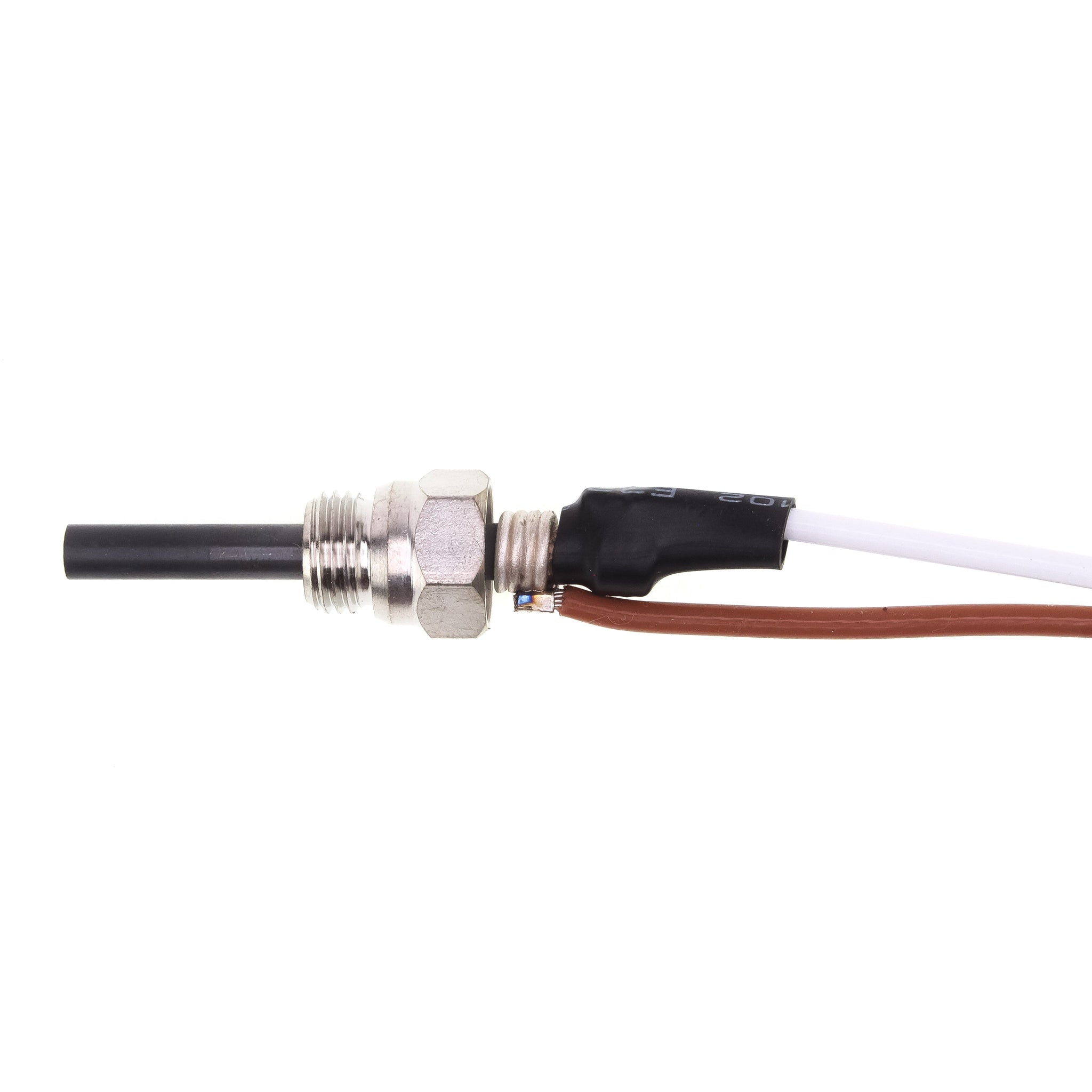
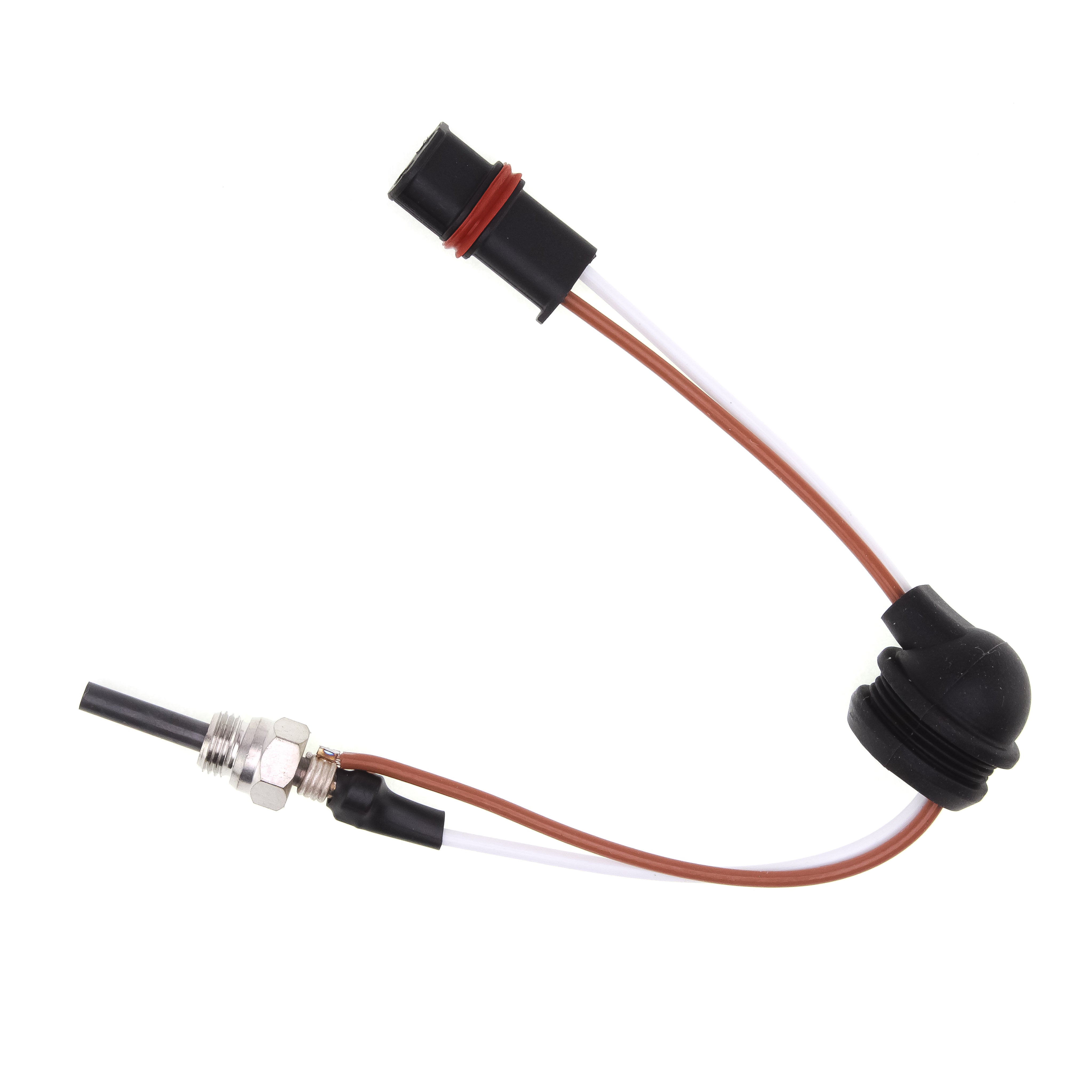
Type of glow plug: brown/white wires & hexagonal head, waterproof connector
* All of the above criteria must be met to qualify for this recall.
NOT ELIGIBLE PRODUCTS:
Model: HEATPORT H2S / H4S
Date of manufacture: 2022/2023
Type of glow plug: brown/white wires & hexagonal head, waterproof connector
Date of manufacture: Mid 2024 and later
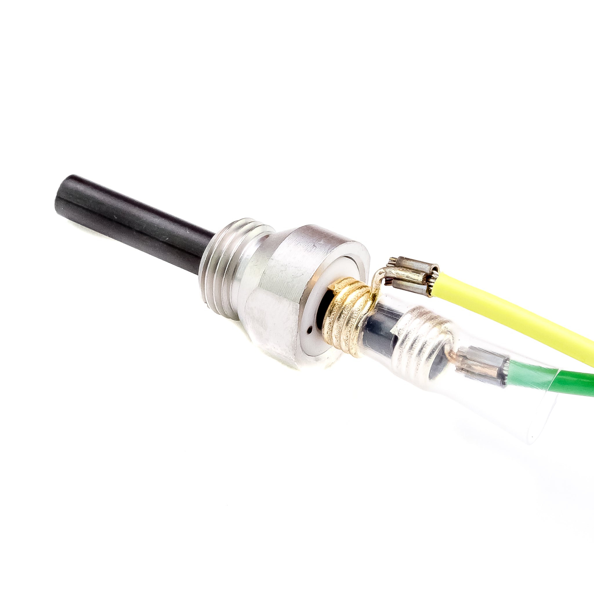
Type of glow plug: green/yellow or blue/yellow wires & flat rounded head, waterproof connector
CAUSE OF PROBLEM
Faulty ceramic pin of the glow plug
Solution: Exchange the glow plug
other possible causes of the same symptom
Glow plug connector disconnected from ECU
Solution: Firmly connect the waterproof connector to the ECU.
Glow plug wiring damaged
Solution: Replace the glow plug
Faulty ECU module
Solution: Replace the ECU module.
How to Determine if Your Glow Plug is Faulty
You may experience the symptoms described above. To confirm whether your glow plug is faulty, follow these steps:
1. Disconnect the waterproof connector from the ECU.
2. Connect the glow plug connector to a laboratory-regulated power supply.
3. Apply a stable voltage:
9V (DC) for 12V versions of your heating unit.
18V (DC) for 24V versions of your heating unit.
4. Maintain this voltage for 20 seconds.
5. Measure the final power draw from the plug.
Results to Observe:
- The ceramic pin of the glow plug should turn red.
- The measured power draw should stabilize around 80W (±15W).
If the glow plug does not meet these criteria, it is likely faulty.
Are all eligible units affected?
No, only a limited number of heating units assembled with the affected production batch of glow plugs are impacted.
Is this a safety issue or risk?
No, the glow plug fault does not pose a safety risk, as this issue prevents the unit from operating altogether.
What Steps Has HEATPORT Taken to Prevent This Fault in New Units?
After identifying the batch of affected glow plugs, we reassembled the remaining stock and began assembling new units with a different model of glow plug from another manufacturer. These new glow plugs, made in Japan by Kyocera, are more stable and are expected to prevent any future issues.
What Does HEATPORT Offer as a Solution for Affected Products?
HEATPORT offers a free supply of the more stable replacement glow plug, manufactured in Japan by Kyocera, along with a removal tool.
How Difficult is it to Replace the Glow Plug?
The replacement process is straightforward and can be completed by the end customer in under 10 minutes, as long as the top of the heating unit is easily accessible. While the replacement does not require a qualified technician, it does require a special tool for removing the old glow plug and inserting the new one. For optimal functionality, it is crucial to follow each step of the instructions below precisely. Additionally, the heating unit does not need to be removed from its installation bottom plate, as long as there is suitable access from the top of the main heating unit.
INSTRUCTIONS FOR REPLACEMENT
DISASSEMBLY INSTRUCTIONS
1. Power Down: Turn off the heating unit and let it cool.
2. Disconnect Power: Safely disconnect the main power supply.
3. Remove Intake Cap or Hose: Remove the round cap on the intake side by turning it anticlockwise, or remove the 60/75mm intake duct hose by loosening the hose clamp.
4. Remove Top Lid: Take off the top plastic lid. For lids with clips, lift them gently until they click, being careful not to break them.
5. Document Wiring: Take a photo of the wire placement around the ECU for reference during reassembly.
6. Remove ECU: Unscrew the socket screw holding the ECU unit with a hex screwdriver.
7. Unlock ECU: Press the two black plastic springs behind the fan turbine to release the ECU, then lift it for full connector access.
8. Disconnect Glow Plug:Disconnect the glow plug connector from the ECU.
9. Expose Glow Plug: Pull out the rubber grommet from the socket and slide it along the wires for easy access.
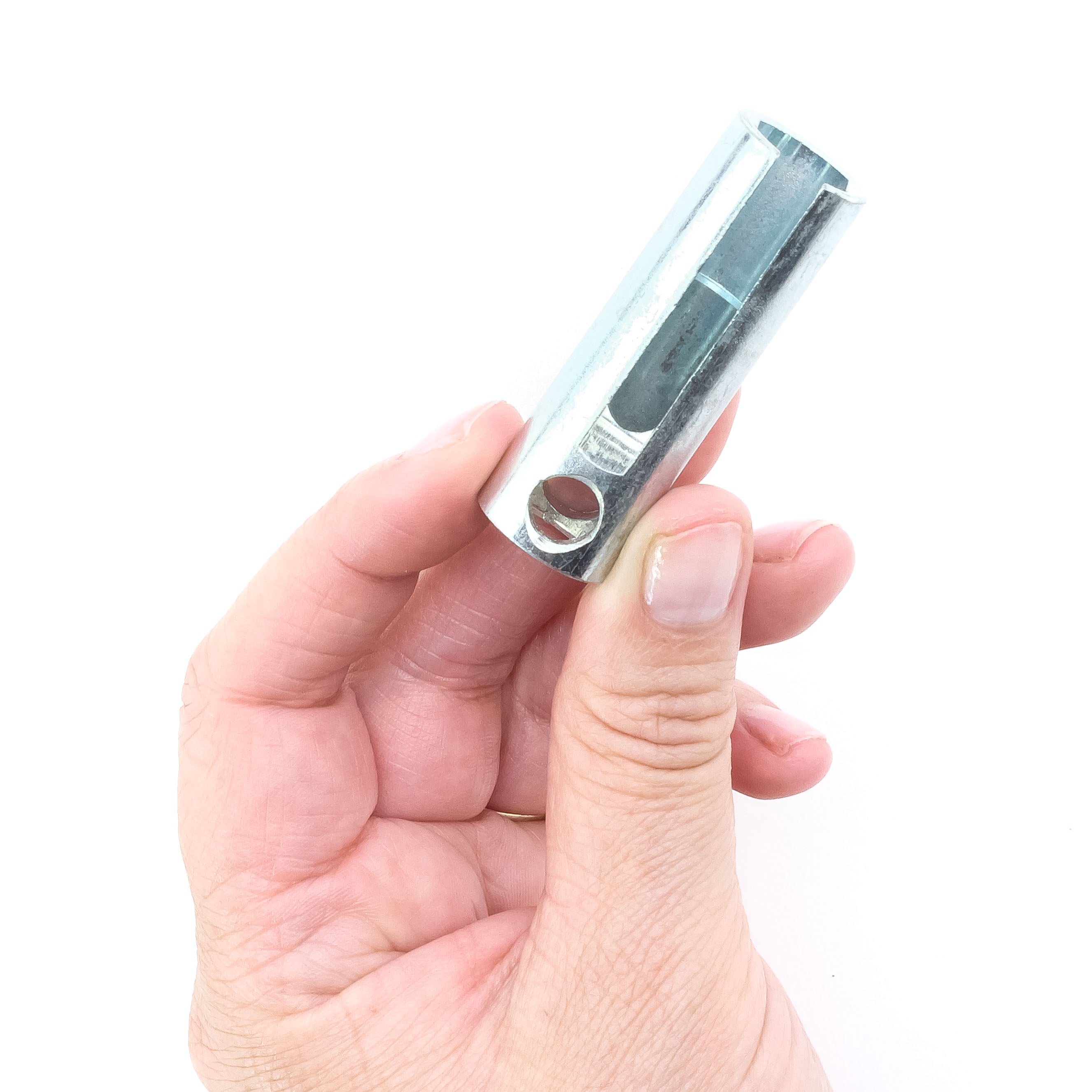
10. Insert Removal Tool: Insert the glow plug removal tool, ensuring the wiring sits in the flat gap. Push the tool in like unscrewing a hex bolt.
11. Remove Glow Plug: Insert a rounded bar (e.g., Phillips screwdriver) into the tool's round hole and turn anticlockwise until the glow plug is removed.

REASSEMBLY INSTRUCTIONS
12. Insert Glow Plug: Insert the new glow plug into the socket and screw it in by hand until it stops spinning, without using the removal tool.
13. Attach Removal Tool: Attach the glow plug removal tool fully to the glow plug head before tightening.
14. Tighten Glow Plug: Insert a screwdriver or round bar into the removal tool and apply the necessary torque. Tighten gently, avoiding over-tightening.
15. Position Rubber Grommet: Carefully slide the rubber grommet all the way in while pulling the wires out, ensuring the wires point toward the air blower motor. Ensure the grommet is tightly sealed in the hole to prevent oxygen leaks, which could negatively impact combustion.
16. Reconnect Glow Plug Connector: Firmly insert the waterproof connector of the glow plug into the ECU, ensuring the wires are routed the same way as before disassembly.
17. Secure ECU: Attach the ECU back to its original position and secure it with the holding screw.
18. Reattach Top Lid: Reattach the top lid and spin the black propeller of the fan to ensure it’s not touching anything inside, like the plastic casing or loose wires.
19. Secure Intake Cap or Duct: Screw the security intake cap back on or reattach the intake duct.
20. Reconnect Power: Connect the power supply and turn on the unit.
RESTART / CLEARING UNBURNED DIESEL:
If the glow plug fault did not trigger an error code and the unit allowed fuel to be pumped in, there is a possibility that the burner and exhaust system could be extensively flooded with unburned diesel. After reassembly, it’s crucial to start the unit using a normal start and wait until it successfully ignites, even if this requires multiple attempts, as it may not start immediately. Set the unit to a fixed power mode on the highest setting.
Initially, you may see white smoke coming from the exhaust. If the exhaust was flooded with unburned diesel, this smoke will not clear after 5-10 minutes but may instead become thicker. This is a positive sign, indicating that the residual diesel is being burned off. It’s important to let the unit run at full power for at least one hour in an exterior space until the white smoke completely clears.
During this clearing process, ensure that no passengers are inside the vehicle, as the intensity of the smoke may cause small amounts of fumes to enter through windows or other openings. It is essential to burn off all residual diesel from the exhaust until the smoke fully clears, which can take anywhere from 10 minutes to an hour, depending on how many times the unit was unsuccessfully started prior replacing the glow plug.
How Can I Obtain the Replacement?
If your heating unit is eligible and you haven’t received the free replacement glow plug yet, please let us know, and we will ship you the replacement glow plug along with the removal tool at no cost.